4 Bit Multiplier Circuit Diagram

Prof. Chauncey Kshlerin

Multiplier reversible adder Bit multiplier binary circuit schematic circuitlab using logic 4 bit multiplier circuit diagram

Solved Redesign the 4-bit parallel multiplier shown in | Chegg.com

Solved Redesign the 4-bit parallel multiplier shown in | Chegg.com

Solved redesign the 4-bit parallel multiplier shown in Multiplier binary circuits Multiplier schematics

4 bit multiplier circuit diagram

How do you explain what code/functions are in terms of electricity : rMultiplier binary multiplication bits circuits adders partial technobyte Multiplier circuit 20p solvedMultiplier digital circuit bit depicts figure.

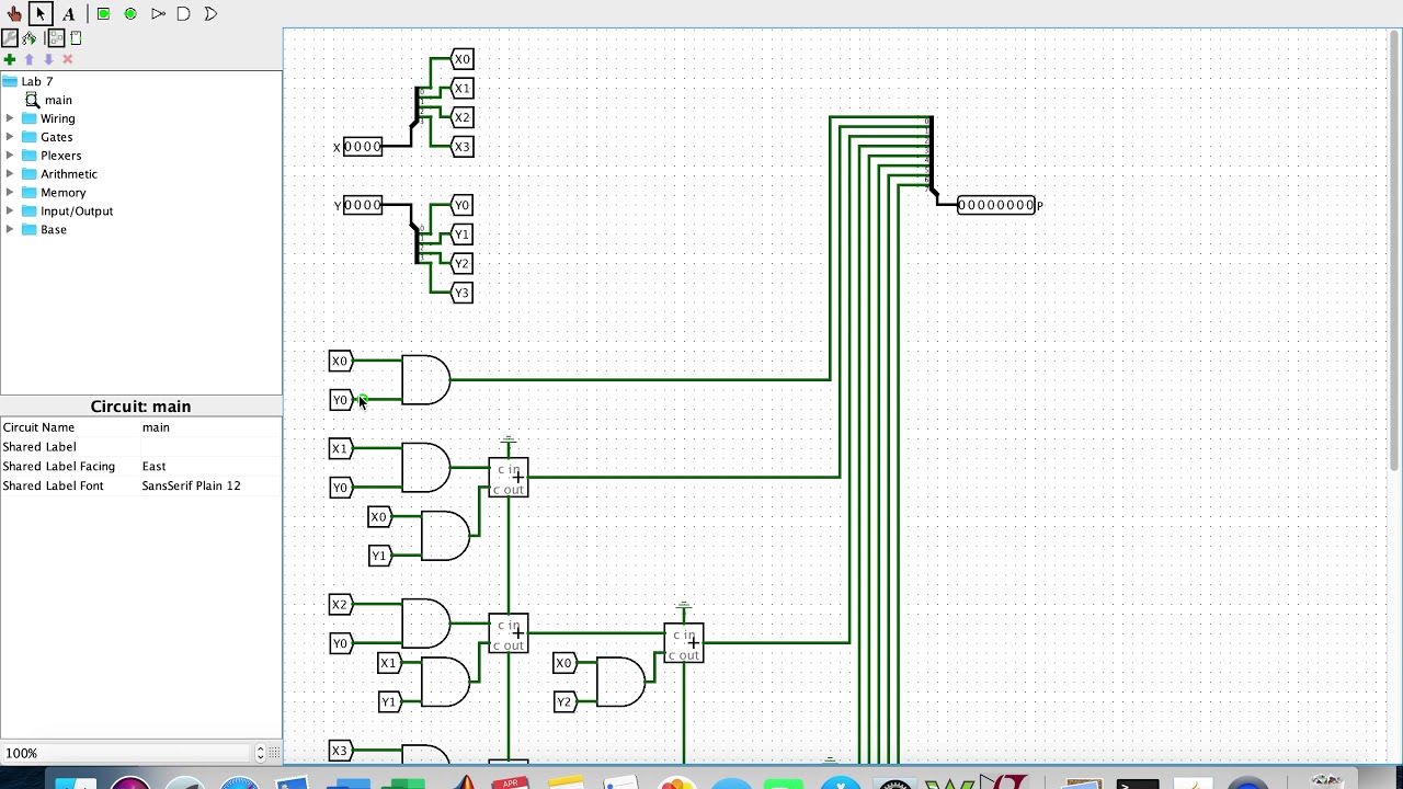
Multiplier explain electricity functions burnt interestingLogisim multiplier bit 4-bit multiplier on logisimMultiplier verilog describe.

4 Bit Binary Multiplier Circuit Diagram - Wiring View and Schematics

4 bit binary multiplier circuit diagram

Multiplier bit parallel redesign shown variable multiply figure used so constant solvedDigital logic 4´4 reversible multiplier circuit in which output of ppgc are input of4 bit multiplier circuit diagram.

Logisim multiplier bit circuit help bits output understand due numberCircuit design Binary bit circuit multiplier adder analysisMultiplier circuit adder logic binary physics forums.

4-bit Multiplier on Logisim - YouTube

4-bit x 4-bit multiplier logic works design

Difference between analog multiplier and digital multiplierBit multiplier logic circuit works using four 4-bit binary multiplier circuit.

.

4-bit binary multiplier circuit - Electrical Engineering Stack Exchange

Difference between Analog Multiplier and Digital Multiplier

digital logic - 4 bit Binary Multiplier - Electrical Engineering Stack

4´4 reversible multiplier circuit in which output of PPGC are input of

Solved Redesign the 4-bit parallel multiplier shown in | Chegg.com

Multiplier - Designing of 2-bit and 3-bit binary multiplier circuits

4 Bit Multiplier Circuit Diagram - Wiring Diagram and Schematics

How do you explain what code/functions are in terms of electricity : r

circuit design - 4 by 4 bit Multiplier. Logisim help - Electrical

4 Bit Multiplier Circuit Diagram - Wiring Diagram and Schematics


YOU MIGHT ALSO LIKE